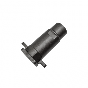
Surface Finish Measuring for iron casting plate

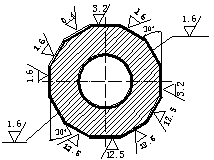
Machining Surface Finish Chart

Machining Surface Finish Chart

Machining surface finish

Machining surface finish is also called surface roughness. It refers to the small spacing and the unevenness of small peaks and valleys of the processed surface. The distance between its two crests or troughs is very small (below 1mm), which is a microscopic geometric shape error. The smaller the surface roughness, the smoother the surface.

Surface roughness is generally formed by the processing method used. At the same time, there are also other factors. For example, the friction between the tool and the surface of the part during the processing, the plastic deformation of the surface layer metal when the chips are separated, and the high-frequency vibration in the process system. Due to the difference in processing methods and workpiece materials, the depth, density, shape and texture of the traces left on the processed surface are different.

Surface roughness is closely related to the matching properties, wear resistance, fatigue strength, contact stiffness, vibration and noise of mechanical parts. And it has an important impact on the service life and reliability of mechanical products. According to international standards, we use Ra for labeling.

Measurement methods

1. Comparative method

The comparative method is simple to measure, and for on-site measurement in the workshop. This method is suitable for measurement on medium or rough surfaces. In brief, the method is to compare the measured surface with a roughness model marked with a certain value to determine the value. The methods that can be used for comparison is as follows. 1. Use visual inspection when Ra>1.6μm. 2. Use a magnifying glass when Ra1.6~Ra0.4μm. 3. Use a comparison microscope when Ra<0.4μm.

When comparing, the processing method, texture, direction, and material of the sample should be the same as the surface of the tested part.

2. Stylus method

Use a diamond stylus with a tip curvature radius of about 2 microns to slowly slide along the measured surface. The up and down displacement of the diamond stylus is converted into an electrical signal by an electrical length sensor. After amplification, filtering, and calculation, the display instrument indicates the rough surface degree value. We can also use the recorder to record the profile curve of the measured section.

Generally, the measuring tool that can only display the surface roughness value is called the surface roughness measuring instrument. And the surface roughness profiler that can record the surface profile curve at the same time. These two measurement tools have electronic calculation circuits or electronic computers, which can automatically calculate the arithmetic mean deviation Ra of the contour, the ten-point height of the microscopic unevenness Rz, the maximum height of the contour Ry and other various evaluation parameters. The measurement efficiency is enough high and is suitable for measuring the surface roughness with Ra of 0.025~6.3 microns.
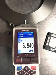
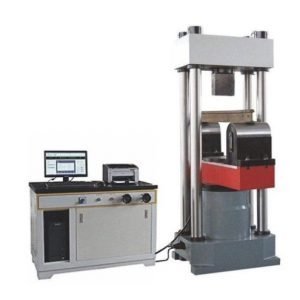
Surface Finish Measuring for iron casting plate

Surface Finish Measuring for iron casting plate

3. Light section

The double-tube microscope measures the surface roughness, which can be used to evaluate Ry and Rz parameters, and the measurement range is 0.5-50.

4. Interference method

Use the principle of light wave interference (see flat crystal, laser length measurement technology) to display the shape error of the measured surface as interference fringe patterns. Meanwhile, use a microscope with high magnification (up to 500 times) to enlarge the microscopic part of these interference fringes Perform measurement to obtain the measured surface roughness. The surface roughness measurement tool using this method is interference microscope. In addition, this method is suitable for measuring surface roughness with Rz and Ry of 0.025 to 0.8 microns.


If you need to know more about related knowledges, please pay attention to our website.

Yide casting is a leading casting foundry in China, with 27 years’ experience, produces top quantity ductile iron castings. If you are interested in our casting fitting, please send us a drawing file, and feel free to get a quite quote.

Detection Methods and Difficulties of Steel Castings

Detection Methods and Difficulties of Steel Castings

Difficulties in detection

1. Poor ultrasound penetration

Coarse grains, uneven structure and other complex interfaces enhance the scattering of ultrasonic waves. And the energy attenuation is large, so that the detectable thickness is smaller than that of forgings.

2. Many interference clutter

When the sound wave is scattered on the uneven, non-dense structure and coarse grain interface, the intensity of the scattered signal is larger and is received by the probe. The rough casting surface will form clutter on the sound wave reflection. These will display on the oscilloscope screen as a messy forest-like echo (also called grass-like echo), which may flood the defect echo and hinder the identification of the defect echo.

3. Poor surface coupling conditions

The surface of the steel casting is rough, which is not conducive to the coupling of sound. At the same time, the surface hardness is large and difficult to polish.

4. Difficult to quantify defects

Due to the large attenuation of sound waves by steel castings and the complicated shape of defects, the quantitative evaluation of defects based on artificial defects has large errors. As a result, it is more difficult to quantify defects by calculation.

The above is exactly the difficulty of casting inspection. These difficulties make casting inspection subject to certain restrictions. But on the other hand, due to the lower quality requirements of castings, single defects are allowed. Meanwhile, the parts where casting defects appear are regular. Therefore, casting detection still has a certain value. 


  • Detection methods

1. Small and medium size castings

For small and medium-sized castings (especially investment precision castings), which are small in size, light in weight, and less processed, they can be magnetized in at least two substantially perpendicular directions on a stationary magnetic particle inspection machine. It is best to use direct current or pulsating direct current, and use the wet continuous method for inspection. Direct energization method, rod-through method, flux method and coil method are all available.

2. Large and heavy castings

For larger and heavier castings, magnetize parts or zones in at least two substantially perpendicular directions. It is best to use a portable or mobile magnetic particle flaw detector with DC or half-wave rectification. And use the contact or yoke method, dry or wet continuous method to detect parts or zones of castings. Testing should generally be carried out in two mutually perpendicular directions.

3. Take the following measures to prevent burning of the castings in contact with the electrodes

when the contacts are not completely in contact with the surface of the castings, no current is connected; and remove the contacts only when the current has been disconnected. In addition, use sufficiently clean and suitable contacts. For smooth and clean surfaces that have been machined, use yoke method.

4. Due to the influence of casting stress, some cracks (cold cracks) of steel castings will delay cracking. Therefore, we should not carry out test immediately after casting, but after 1 to 2 days.

5. If the casting is rejected due to the defect exceeding the acceptance criteria, and digging (shoveling) and repair welding are allowed, the repair welding area should also pay attention to control the delayed cracks.

6. The inspection should be done with the naked eye. And magnifying glass less than 3 times can be used only in the inspection of 001 and 01 quality levels.


Yide casting is a leading casting foundry in China, with 27 years’ experience, produces top quantity steel castings. If you are interested in our casting fitting, please send us a drawing file, and feel free to get a quick quote.

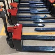
lead acid battery pallet jack

The Development History of Logistics Pallet Trucks

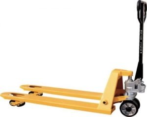
The pallet truck is the logistics handling equipment that transport goods. The development history of pallet trucks has experienced three generations, and is developing to the fourth generation.

1. Manual Pallet Jacks

The first-generation pallet truck is a manual pallet truck. It is characterized by a low degree of automation and intelligence. However it has made a huge contribution to the conversion of manual handling to mechanized handling. Today, it is still in the pallet truck market, and take a certain market share.


2. Internal Combustion Pallet Trucks

The second-generation pallet truck is the internal combustion pallet truck. The 2nd generation is represented by the internal combustion forklift, which has high automation. The internal combustion forklift is powered by the engine and has strong power. The disadvantage is that the exhaust emission pollutes the environment, and the efficiency is low. Besides, it is harmful to human health. Thus it is not suitable for use in the food industry.

3. Electric Pallet Trucks

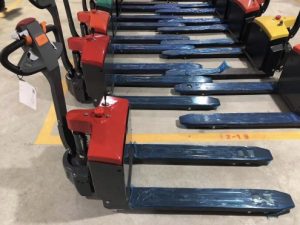
The third-generation pallet truck is all-electric pallet truck. Its degree of automation is equivalent to that of internal combustion pallet truck. However the electric pallet jack is a power technology update based on the concept of energy saving and environmental protection. It uses battery power and has the advantages of energy saving, no exhaust gas emissions, and low noise. It is the best choice for food industry. Due to its outstanding advantages of energy saving, it is considered by the truck industry as one of the most potential handling equipment in the future.


4. Automated Guided Vehicles System

The development of the fourth-generation transport vehicle is represented by automated guided vehicles system, referred to as AGVS. AGVS is expected to be widely used in the 1950s. It is an effective means of logistics transportation in today’s flexible manufacturing system (FMS) and automated warehouse system.

Modern AGVs are controlled by computers. Most AGVS is equipped with a centralized control and management computer for the system. The system is used to optimize the operation process of the AGV and issue handling instructions. At the same time, it can also track the components in transmission and control the route of the AGV. The guidance methods of unmanned vehicles mainly include electromagnetic induction guidance, laser guidance and magnet gyro guidance. We can input program to guide the vehicle to complete the handling work. AGVS is a kind of truck with higher intelligence.

Daily Maintenance of 5 Key Parts of Manual Hydraulic Pallet Truck

The manual pallet truck is undoubtedly a common handbarrow in modern logistics, which is found in factories of all sizes. It is also widely used in various industries such as postal services, airports, warehouses, workshops and supermarkets. In a modern society, the handling of materials is inseparable from manual pallet trucks. Thus the truck is also called “the king of land”.

In the process of social development and changes, the demand for manual pallet trucks is also undergoing new changes, and the number of companies with personalized needs is gradually increasing. Various types of trucks appear in the market, in order to meet market demand, such as: widened manual trucks, large-tonnage manual trucks, scissor manual trucks, electronic scale trucks, electric trucks, etc.

However, all types of manual pallet trucks are faced with a problem. That is, the after-sales service and maintenance of manual pallet trucks. As the saying goes: there is nothing in the world that is not bad. No matter how good the product is, there are times when it is damaged or eliminated. Therefore, solving the after-sales service maintenance problem is the guarantee for the continuous operation of the manual pallet truck.

Today, Yide Casting will give you an analysis of the 5 key parts that are prone to having problems. And above all, how to solve these problems.

iron casting oil pump

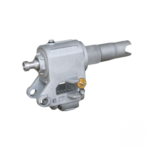
1. Oil pump

The oil pump is a key part of all trucks. Once there is a problem with the oil pump, it means that the truck is declared to stop working. Even though the other parts are good and without any damage. The oil pump consists of a lot of parts. Among them, dust-proof rings, O-rings, steel balls and other parts are prone to having problems. Once problems with these parts are found, the quicker solution is to replace these accessories.

hand pallet truck cylinder
2. Oil cylinder

The oil cylinder plays a vital role in the entire lifting process of the truck. And it is also used to rise and fall the goods. Therefore, if the fork cannot be lowered or raised, the reasons are: 1. The piston rod and the oil cylinder may be damaged due to overload or partial load during the load; 2. The piston rod is exposed for a long time and rusts, thus hinder the smooth movement of the piston; 3. The adjusted nut and hex nut are not in the correct position. At this time, we should replace the piston rod or cylinder, lower the truck to the lowest level when the truck is not used, and readjust the nut.

3. Oil seal

The oil seal is the key component between the piston rod of the oil cylinder and the cylinder barrel. Imported sealing rings are generally used. Mainly because of good sealing performance, wear resistance and long service time. And 70% of the oil leakage of the oil cylinder occurs on the oil seal. If oil leakage is found in the oil cylinder, check it in time. If the sealing ring is aging or damaged, replace it with a high-quality one.

4. Wheels

Handling wheels will wear out if they are used for a long time. There are also many kinds of wheels for handling vehicles, such as nylon wheels, PU wheels, polyurethane coated nylon, rubber wheels, bakelite, etc. Most trucks are equipped with nylon wheels because they are common in the market and cheap, but they are less worn and noisy when walking. Please replace the transport wheels in time if they are worn to a certain extent.

5. Lever frame

The lever frame is the key component connecting the oil pump and the push rod. The lifting support of the hydraulic cylinder and the carrying and loading of goods are supported by the lever frame to achieve a balance. Because of the possibility of overloading and unbalanced loading when handling goods, which often lead to deformation or fracture of the lever frame. Once this happens, the truck cannot operate normally. At this time, you contact the manufacturer or purchase a replacement lever frame.