Machining Surface Finish Chart
Machining Surface Finish Chart
Machining surface finish
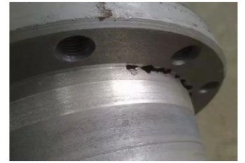
Machining surface finish is also called surface roughness. It refers to the small spacing and the unevenness of small peaks and valleys of the processed surface. The distance between its two crests or troughs is very small (below 1mm), which is a microscopic geometric shape error. The smaller the surface roughness, the smoother the surface.
Surface roughness is generally formed by the processing method used. At the same time, there are also other factors. For example, the friction between the tool and the surface of the part during the processing, the plastic deformation of the surface layer metal when the chips are separated, and the high-frequency vibration in the process system. Due to the difference in processing methods and workpiece materials, the depth, density, shape and texture of the traces left on the processed surface are different.
Surface roughness is closely related to the matching properties, wear resistance, fatigue strength, contact stiffness, vibration and noise of mechanical parts. And it has an important impact on the service life and reliability of mechanical products. According to international standards, we use Ra for labeling.
Measurement methods
1. Comparative method
The comparative method is simple to measure, and for on-site measurement in the workshop. This method is suitable for measurement on medium or rough surfaces. In brief, the method is to compare the measured surface with a roughness model marked with a certain value to determine the value. The methods that can be used for comparison is as follows. 1. Use visual inspection when Ra>1.6μm. 2. Use a magnifying glass when Ra1.6~Ra0.4μm. 3. Use a comparison microscope when Ra<0.4μm.
When comparing, the processing method, texture, direction, and material of the sample should be the same as the surface of the tested part.
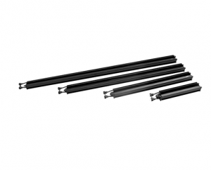
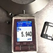
2. Stylus method
Use a diamond stylus with a tip curvature radius of about 2 microns to slowly slide along the measured surface. The up and down displacement of the diamond stylus is converted into an electrical signal by an electrical length sensor. After amplification, filtering, and calculation, the display instrument indicates the rough surface degree value. We can also use the recorder to record the profile curve of the measured section.
Generally, the measuring tool that can only display the surface roughness value is called the surface roughness measuring instrument. And the surface roughness profiler that can record the surface profile curve at the same time. These two measurement tools have electronic calculation circuits or electronic computers, which can automatically calculate the arithmetic mean deviation Ra of the contour, the ten-point height of the microscopic unevenness Rz, the maximum height of the contour Ry and other various evaluation parameters. The measurement efficiency is enough high and is suitable for measuring the surface roughness with Ra of 0.025~6.3 microns.
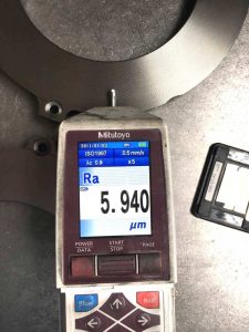
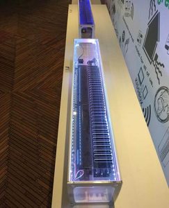
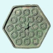
Surface Finish Measuring for iron casting plate
3. Light section
The double-tube microscope measures the surface roughness, which can be used to evaluate Ry and Rz parameters, and the measurement range is 0.5-50.
4. Interference method
Use the principle of light wave interference (see flat crystal, laser length measurement technology) to display the shape error of the measured surface as interference fringe patterns. Meanwhile, use a microscope with high magnification (up to 500 times) to enlarge the microscopic part of these interference fringes Perform measurement to obtain the measured surface roughness. The surface roughness measurement tool using this method is interference microscope. In addition, this method is suitable for measuring surface roughness with Rz and Ry of 0.025 to 0.8 microns.
If you need to know more about related knowledges, please pay attention to our website.
Yide casting is a leading casting foundry in China, with 27 years’ experience, produces top quantity ductile iron castings. If you are interested in our casting fitting, please send us a drawing file, and feel free to get a quite quote.